
 The “Attribute” window is the window for confirming and setting the information of the parts selected in the current Frame Control Window.
This window is comprised of the information of the following three groups.
By clicking the “round with chevron” mark located at the front of the group name, the Open/Close can be switched alternately.
The  indicates the group is open. The
  indicates the group is closed.
The above figure (all the groups) are closed normally for easier work, but all the groups are open at the initial stage of activating “OPTPiX SpriteStudio” at first.
Parts Information
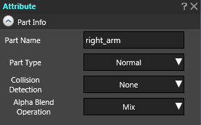 In the groups of the “Parts Information”, the information of the parts itself is contained. This information cannot be changed in the midway of animation.
Parts Name (String Input)
This is the parts name on the animation data. By rewriting this name, the parts name can be changed.
Parts Type
This is for selecting the type of parts. Click the item and select the type of the parts.
- NULL Parts
- It sets the parts as the NLL parts. The NULL parts are the parts of Hide, which is unrelated to the display. So, when the parts are normally changed to NULL parts, it will not be displayed on the animation.
- Normal Parts
- It sets the parts as a normal parts. The normal parts is the parts for showing the cell assigned to itself as one drawing parts.
Collision Detection
It selects the collision detection attached to the parts. By clicking the item name, select the type of collision detection. Also, when the range of the collision detection is set so as to set the “Show Collision Detection” in the layout window, it is shown in the translucent red color.
- None
- No collision detection is attached.
- Quadrangle
- It takes the quadrangle with the same size of the parts as its collision detection range. The collision range of this method works jointly with the deformation of the parts (zoom up/down, rotation, move of position, etc.).
- AABB
- After a parts is made to deformation of the parts (zoom up/down, rotation, move of position, etc.), it takes the Quadrangle circumscribed with the related area as its collision detection range. The AABB is the abbreviation of “Axis-Aligned Bounding Box”, meaning “parallel to the axis, quadrangle circumscribed with the boundary”. It is always a shape parallel to the axis, and the quadrangle never rotates even if the size changes in accordance with the shown state of parts.
- Circle (Absolute value)
- It creates a circle at the parts’ origin, taking the attribute’s “Collision Radius” as its radius size. By this method, the collision range works jointly with changes of coordinates of the parts’ position but the size shall not be affected except by the “Collision Radius”.
- Circle (Scale uses the minimum)
- It creates a circle at the parts’ origin, taking the attribute’s “Collision Radius” as its standard size. By this method, the collision range works jointly with changes of coordinates of the parts’ position. Also, the radius size is the multiplication of the smallest of the “X Scale” and “Y Scale” and the “Collision Radius”.
- Circle (Scale uses the maximum)
- It creates a circle at the parts’ origin, taking the attribute’s “Collision Radius” as its standard size. By this method, the collision range works jointly with changes of coordinates of the parts’ position. Also, the radius size is the multiplication of the largest of the “X Scale” and “Y Scale” and the “Collision Radius”.
Alpha Blend Operation
When drawing the parts, it sets how the alpha blending to be implemented. Click the item name and select the alpha blending method. To be noted, there is a case that a part of the parameters cannot be selected due to the setting of “Compatibility”.
- Mix
- To the pixel colors available in the parts’ reference cells, a color with setting of the attribute’s “Color Blend” is blended into the image in consideration of the “Opacity”. This blending method is the most popular method.
- Multiplication
- To the pixel colors available in the parts’ reference cells, a color with setting of the attribute’s “Color Blend” is multiplied in consideration of the image’s already-drawn color (background color) and the “Opacity”. By this blending method, when the blended color (The opacity is 1.0.) is “White, No affect” and “Black, Complete Black”. In this manner, the darker the blended color, the darker the result.
- Addition
- To the pixel colors available in the parts’ reference cells, a color with setting of the attribute’s “Color Blend” is added in consideration of the image’s already-drawn color (background color) and the “Opacity”. By this blending method, when the blended color (The opacity is 1.0.) is “Black, No affect” and “White, Complete White”. In this manner, the brighter the blended color, the brighter the result.
- Subtraction
-
To the pixel colors available in the parts’ reference cells, a color with setting of the attribute’s “Color Blend” is subtracted in consideration of the image’s already-drawn color (background color) and the “Opacity”. By this blending method, when the blended color (The opacity is 1.0.) is “Black, Complete White” and “White, Complete Black”. In this manner, the brighter the blended color, the darker the result.
This blending method can be rephrased as follows: “Mix blending by flipping the RGB values of the blending color”.
-
General
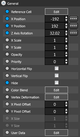 In the “General” Group, the information setting of the key frame in the animation’s data is enabled. Accordingly, the items inside this group can be set only in the frame in which the key frame exists.
- Meaning of the round mark in front of the respective attributes
- The round mark in front of the respective attributes indicates the two kinds of the state: “Light Gray” and “Blue”. The “Blue” means that the attribute has been set in the key frame. The “Light Gray” means that the attribute has not been set in the key frame. The attribute of the light gray throughout the whole animation is judged as unused.
When a value is set to the attribute or when the light gray mark is clicked, it turns to blue meaning it is at the use state. To the contrary, when the blue round mark is clicked, it turns to light gray and the attribute can be made at the unused state.
- The round mark in front of the respective attributes indicates the two kinds of the state: “Light Gray” and “Blue”. The “Blue” means that the attribute has been set in the key frame. The “Light Gray” means that the attribute has not been set in the key frame. The attribute of the light gray throughout the whole animation is judged as unused.
- Value Input in Input Column
- When the input column exists at the side of the attribute name, the value can be directly input from the keyboard by clicking inside the box.
- Mouse Operation of Value Box
- When the input column exists at the side of the attribute name, the value can be changed by maintaining the click of the attribute name and moving cursor (dragging). Dragging to the top or right, the numeric value increases, and bottom or left, the numeric value decreases.
- The [Set] button exists at the side of the attribute name
- When there is the [Set] button at the side of the attribute name, the setting dialog will open by clicking this button and the attribute value can be entered thereto.
- The checkbox exists at the side of the attribute name
- When there is the checkbox at the side of the attribute name, the ON/OFF of the effects of the attribute can be switched alternately by clicking the checkbox.
- About Attribute’s Interpolation
- When the attribute is at the use state (blue round mark), the [—-] button appears to the attribute indicating it can be interpolated. By clicking this button, the window called “Curve Editor” for interpolation setting will open. So, the required setting is done here. How to use the “Curve Editor” can be referred to “Curve Editor (Interpolation Setting)”.
With the above basic operation in mind, the following is an explanation of the content of the respective attributes.
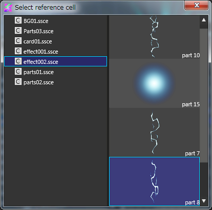
| Reference Cell |
It sets the cell referenced by the corresponding parts, after the related key frame. The left side to the setting window of the reference frame is the cell map, and the right side the cell list. By selecting them, the setting is enabled.
|
|---|---|
| X Position | The parts’ X coordinate in the key frame is set at the unit of pixel. The origin of the used reference cell is snapped to this X coordinate. The parts’ X coordinate in the key frame is set at the unit of pixel. The origin of the used reference cell is snapped to this X coordinate. |
| Y Position | The parts’ Y coordinate in the key frame is set at the unit of pixel. The origin of the used reference cell is snapped to this Y coordinate. |
| Z Position |
The parts’ Z coordinate in the key frame is set. The unit of the Z coordinate solely depends upon the application side that mounts data (treated as the unit called the “World Coordinate System” as cited by 3DCG). The origin of the used reference cell is snapped to this Z coordinate.
|
| X Axis Rotation | The parts is rotated taking the X axis passing the origin of the currently-used reference cell as its axis. The unit is “Angle”. |
| Y Axis Rotation | The parts is rotated taking the Y axis passing the origin of the currently-used reference cell as its axis. The unit is “Angle”. |
| Z Axis Rotation |
The parts is rotated taking the Z axis passing the origin of the currently-used reference cell as its axis. The unit is “Angle”. Normally, this attribute is used to rotate the 2D Sprite. |
| X Scale |
It sets the parts’ horizontal scale taking the origin of the currently-used reference cell as its central point. The unit is the “Proportion”, and it is actual sizes of the reference cell that is used at 1. When the minus (negative) value is set, it becomes at the state of Right and Left Flip.
|
| Y Scale |
It sets the parts’ vertical scale taking the origin of the currently-used reference cell as its central point. The unit is the “Proportion”, and it is actual sizes of the reference cell that is used at 1. When the minus (negative) value is set, it becomes at the state of flipped top and bottom.
|
| Opacity |
It sets the opacity when parts are shown. With 1, complete opacity (the reference cell’s pattern design is as is.), and with 0, complete transparency (Same as not shown.). This attribute is for translucent blending. etc. In case of the simple Parts’ Show/Hide switching, it is recommended to use the “Hide” attribute instead of this attribute. |
| Priority |
It sets the priority of display. The range possible to specify is -9999 – 9999. With -9999, the drawing is done at the earliest (in the back) and with 9999 (in the front). In principle, the higher value, the more frontal the display is made. However, depending upon the mounted game engines and the hardware specifications, there is the case that the display state will be different from the the state of “OPTPiX SpriteStudio”. When this is used together with the Z axis, confirm the specifications of the mounted application carefully. |
| Horizontal Flip |
It sets the Right and Left Flip of the display state (Texture Mapping) of the reference cell inside the Parts. If the check is attached, it becomes right and left flipped and if the check is removed, the state turns to be not flipped. Unless specified in particular, this Right and Left Flip is applied only to parts but not inherited to child parts. With the “Inheritance Setting” at its child parts side, set the “Horizontal Flip” ON in order to enable inheritance. |
| Vertical Flip |
It sets the Top and Bottom Flip of the display state (Texture Mapping) of the reference cell inside the Parts. If the check is attached, it becomes top and bottom flipped and if the check is removed, the state turns to be not flipped. Unless specified in particular, this Top and Bottom Flip is applied only to parts but not inherited to child parts. With the “Inheritance Setting” at its child parts side, set the “Vertical Flip” ON in order to enable inheritance. |
| Hide |
The parts are not shown. If the check is attached, it becomes Hide. If it is removed, it becomes Show. Unless specified in particular, this Hide setting is applied only to parts but not inherited to its child parts. With the “Inheritance Setting” at the child parts side, set the “Hide” ON in order to enable inheritance. |
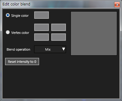
| Color Blend |
It specifies the effect of covering (overlay) the color onto the parts. This is the function to process the pixel color from over it, maintaining the pattern design of the reference cell used in the parts as it is. By clicking the [Setting], the following exclusive-use dialog opens.
With this dialog, the method of color blending is chosen.
|
| Vertex Deformation |
On the basis of the parameter setting, the “Concave Type (like a boomerang shape)” and “Twisted Type” can be created. However, when such shapes are specified, there may happen the case that the normal display state (or as anticipated) cannot be attained depending upon the differences of the mounted game engines and hardware. So, a care must be taken. |
| X Pivot Offset | It sets the relative value so as to temporarily slide the origin X coordinate of the parts’ reference cell. The unit to be set must be the “Regulating Texture Coordinate System (The UV Coordinate System)”, and it becomes the ratio position where the horizontal width of the reference image of the cell map to which the reference cell belongs is set at 1.0. |
| Y Pivot Offset | It sets the relative value so as to temporarily slide the origin Y coordinate of the parts’ reference cell. The unit to be set must be the “Regulating Texture Coordinate System (The UV Coordinate System)”, and it becomes the ratio position where the horizontal width of the reference image to which the reference cell belongs is set at 1.0. |
| X Anchor | When a special parts having the anchor function is created, the anchor’s X position is set by the “Parent Parts’ Regulation Coordinates”. The “Parent Parts’ Regulation Coordinates” is the ratio position where the center is (0,0), the Left Top is (-0.5, 0.5) and the Right Bottom is (0.5, -0.5). This function is a very special function and it is not used normally. If it is used inevitably, be very sure to refer to the after-mentioned “Special Parts having Anchor Function” and use it after grasping its specialty and the purpose of its function. |
| Y Anchor | When a special parts having the anchor function is created, the anchor’s Y position is set by the “Parent Parts’ Regulation Coordinates”. The “Parent Parts’ Regulation Coordinates” is the ratio position where the center is (0,0), the Left Top is (-0.5, 0.5) and the Right Bottom is (0.5, -0.5). This function is a very special function and it is not used normally. If it is used inevitably, be very sure to refer to the after-mentioned “Special Parts having Anchor Function” and use it after grasping its specialty and the purpose of its function. |
| X Size | When a special parts having the anchor function is created, the size of the parts’ X direction is set by the ratio. This function is a very special function and it is not used normally. If it is used inevitably, be very sure to refer to the after-mentioned “Special Parts having Anchor Function” and use it after grasping its specialty and the purpose of its function. |
| Y Size | When a special parts having the anchor function is created, the size of the parts’ Y direction is set by the ratio. This function is a very special function and it is not used normally. If it is used inevitably, be very sure to refer to the after-mentioned “Special Parts having Anchor Function” and use it after grasping its specialty and the purpose of its function. |
| UV X Translation | It offset-transports the horizontal direction (U coordinates) of the UV Coordinate of the parts’ reference cell. The unit to be set is “Regulating Texture Coordinate System (The UV Coordinate System)”, and it becomes the ratio position where the horizontal width of the reference image of the cell map to which the reference cell belongs is set at 1.0. |
| UV Y Translation | It offset-transports the vertical direction (V coordinates) of the UV Coordinate of the parts’ reference cell. The unit to be set is “Regulating Texture Coordinate System (The UV Coordinate System)”, and it becomes the ratio position where the vertical width of the reference image of the cell map to which the reference cell belongs is set at 1.0. |
| UV Rotation | It sets the rotation angle upon mapping the parts’ reference cell. The parts itself does not rotate and only the pattern design inside rotates. |
| UV X Scale | It sets the zoom up/down ratio of the horizontal direction of the UV Coordinate of the parts’ reference cell. |
| UV Y Scale | It sets the zoom up/down ratio of the vertical direction of the UV Coordinate of the parts’ reference cell. |
| Collision Radius | When the circle was selected by the “Collision Detection”, the radius of the circle of the collision range can be set by this attribute. The actual collision range changes depending upon the kinds of the circle set by the “Collision Detection”. So, refer also to the explanation of the “Collision Detection of the Parts Information”. |
| User Data |
This is the data the user can define optionally. This is used mainly for joint-work and communication with the application program that implements the created data. The data possible to be set are four kinds: “Numeric Value”, “Rectangle”, and “Coordinates”, “String”. The data with the check mark attached becomes effective. Plural data can be selected.
The input data with the check mark at front becomes effective (plural selection possible).
|
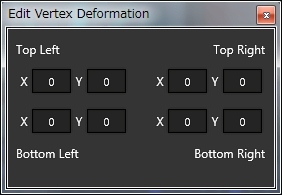 By specifying the coordinates of “Left Top”, “Right Top”, “Left Bottom” and “Right Bottom”, the parts can be processed to optionally-shaped quadrangle.
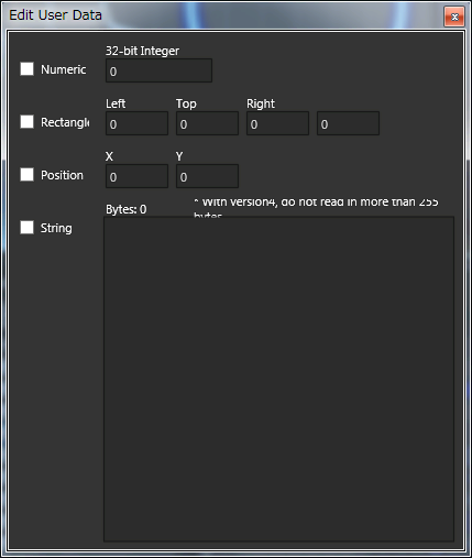
About the “Special Parts having Anchor function”
Among a number of the attributes, the “X Anchor”, “Y Anchor”, “X Size” and “Y Size” possess special uses. Also, the parts using these attributes do special behaviors compared with the other parts not using them. These attributes are prepared mainly to set the “Fixed Layout with Child Parts”. Concretely, the parts using these attributes give the following influences to their child parts.
- With the child parts’ coordinates, the reference position is the value added by the parent parts’ “X/Y Coordinates” and “X/Y Anchor”.
- Same as the normal parts, various attributes’ value is inherited. So, when the X/Y Scaling, etc. is operated, the deformation occurs, same as the normal parts (influenced by the parent parts).
- However, the child parts is never influenced by the “X/Y Size” of the parent parts (not inherited).
This means that as long as the parent parts is zoomed up/down by using “X/Y Size”, the child parts can create a special layout without being is affected by the “Position and Size”. As a typical example of creating Sprite by using this attribute, there is the “User Interface such as the size of the button and position are not affected by the changes of the size of the base”.
However, if the “X/Y Anchor” and “X/Y Size” attributes are mixed in the attribute setting of the normal animation, there may be the case that the child parts group and the whole animation happen to do unexpected behaviors and the movements of the whole animation cannot be grasped.
Therefore, the design of the parts configuration must be well considered and a minute care must be taken.
Inheritance Setting
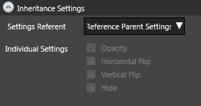 With this inheritance setting, whether the parent’s inheritance setting is referenced or not is set.
Reference Destination of Setting
It sets whether the parent’s inheritance setting is referenced or not is selected.
Refer To Parent Setting
It uses the inheritance setting of the self’s parent. When the parent parts uses also this setting, the parent parts’ setting is used additionally. If having gone back to the root parts, it is treated as all the “Opacity”, “Horizontal Flip”, “Vertical Flip” and “Hide” are not inherited (Same as the pre-checked state).
Use Individual Settings
Whether parent’s inheritance setting is referenced or not is specified per parts. The setting is enabled with the following attributes. Other attributes than those are inherited compulsorily. Attach the check mark to the items with which parent’s inheritance setting is preferred.
- Opacity
- Horizontal Flip
- Vertical Flip
- Hide
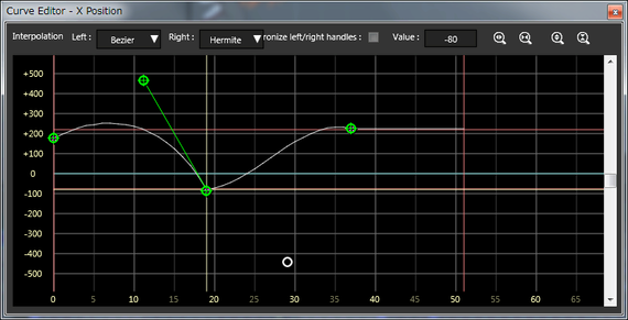
Curve Editor (Interpolation Setting) Window
With the “Curve Editor”, the changing method of the parts’ in-between value can be set visually.
The interpolation method is to set the “Right” and “Left” of the key frame separately. However,
- The “Left” is the same as the setting of the “Just-before Key Frame’s Right”
- The “Right” is the same as the setting of the “Just-after Key Frame’s Left”
So, a cared must be taken.
Interpolation Method
It sets the method of interpolation calculation between key frames.
- None
- No interpolation. The value will be switched immediately when it becomes its key frame.
- Linear
- It interpolates between key frames linearly. The linear interpolation, as its name, calculates so as to change the section at the equal speed.
- Hermite
- It interpolates between key frames by the three-dimensional curve. The three-dimensional curve is the curve changing like the “S Letter”. It operates the shape of the curve by adjusting the slant and the length of the green handle that is written at the Start and End points on the Curve Editor.
- Bezier
- It interpolates between the key frames by the curve called “Bezier Curve”. The Bezier curve becomes the curve so as to draw a mountain-type shape into the quadrangle formed by the “Start Point”, “End Point”, “Handle’s Front Edge of the Start Point” and “Handle’s Front Edge of the End Point”.
- Acceleration
- It draws a curve so as to make general acceleration.
- Deceleration
- It draws a curve so as to make general deceleration.
Synchronize left/right handles
When, on the curve editor, the key frame is created in the mid of the curve, the handle to specify the interpolation slant of the created key frame is necessary to be “set separately taking the right and left respective key frames as an object” but it makes this as “the direction becomes opposite with the right and left handles’ slant and length as same”.
Value
This is the value possessed by the attribute of the key frame handled currently. The attribute value can be specified directly hereto.
Scale’s Zoom Up/Down
By clicking the button located at the neighboring right of the “Value”, the scale’s zoom-in and zoom-out is enabled.
About Key Frame Operation
The key frame’s operation on the curve editor is enabled as follows:
- Move (Translation)
- By clicking and dragging key frame horizontally, the frame’s position of the key frame can be changed. By moving it vertically, the attribute value possessed by the key frame can be changed.
- Add
- By clicking the mid of the curve line, a new key frame can be created at that position.
- Delete
- By pressing DELETE key after clicking the key on the curve, the selected key can be deleted.