
The Layout Window shows the layout state of the frame specified in the Frame Control Window. You can also edit the layout of that frame.
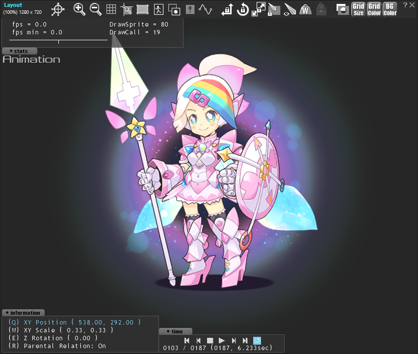
The Layout Window is roughly divided into 2 parts, “toolbar” and “Display portion of the layout”.
Operation By Toolbar
The toolbar contains buttons that control various display changes, and assist in manipulating Part.
|
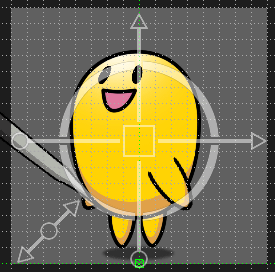
Displays a gizmo (Handle to manipulate the Part). A blue background shows the gizmo, while a gray background hides it. The display switches each time you click the button. Drag the arrow at the end of the cross to move the part. Drag a vertical arrow to move vertically, or drag a horizontal arrow to move horizontally. Drag the circle at the end of the cross to scale the part vertically and horizontally. Drag the circle at the end of the vertical line to increase or decrease the height. Drag the circle at the end of the horizontal line to increase or decrease the horizontal width. Drag the diagonal arrow at the bottom left to scale the part proportionally. Drag the circle to rotate the part. |
|
|
Increases the magnification of the display. The display magnification can be up to 1600%. |
|
|
Decreases the magnification of the display. The minimum magnification is 5%. |
|
|
Shows or hides the grid. If the button background color is blue, the grid is visible; if the button background color is gray, the grid is invisible. |
|
|
Snap the Pivot of the Part to the grid when changing the position of the Part in the Layout Window. A blue button background snaps to the grid; a gray button background does not. Snap is toggled on and off each time you click the button. |
|
|
Shows or hides the Reference Frame. The background color of the button is blue to show the Reference Frame, and gray to hide the Reference Frame. Each time you click the button, the Reference Frame is displayed or hidden. |
|
|
Shows or hides the Focus Frame for the selected Part. A blue background indicates that the Focus Frame is displayed, and a gray background indicates that the Focus Frame is not displayed. Each time you click the button, the Focus Frame is displayed or hidden. |
|
|
Switches between normal and outline display for parts other than the selected part. When the background color of the button is blue, only the outline is displayed. When the background color is gray, the normal display is performed. The display changes every time you click the button. |
|
|
Shows or hides the Collision Detection area. The area of the Collision Detection set for each Part is displayed in a red translucent color. |
|
|
Shows or hides the Move Path. The background color of the button is blue to show the Move Path, and gray to hide the Move Path. |
|
|
Locks the Part so it does not move. A blue background color indicates that movement is locked, and a gray background color indicates that movement is allowed. |
|
|
|
Locks the Part so that it does not rotate. A blue background color indicates locked rotation; a gray background color indicates enabled rotation. |
|
|
Locks the scale of the Part so that it does not change. A blue background indicates that the scale is locked, and a gray background indicates that the scale can be changed. |
|
|
Locks Parts other than Bone Parts so that they cannot be modified. A blue background indicates locked editing; a gray background indicates enabled editing. |
|
|
Shows or hides the Bone Part. A blue background color shows the Bone Part, and a gray background color hides the Bone Part. |
|
|
Displays the weight status on the Mesh Part. Displays the state of the weights that indicate the influence of the Bone Part in the Bone Part Color. |
|
|
Reset the weight. If the mesh part does not change correctly, or if the weight is not displayed as expected, press this button to reset the weight. |
|
|
Enables the Mask Feature. When enabled, the Mask Feature represents the effect. In the disabled state, the Mask Part looks like a normal Part. |
|
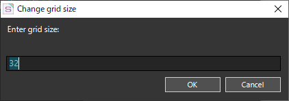
The “Change Grid Size” dialog opens. The “Change Grid Size” dialog allows you to set the grid to any pixel size by specifying a number from 2 to 256. |
|
|
Changes the color of grid lines. Opens the Color Picker Window so you can set the color of the grid lines by specifying any color. |
|
|
Changes the background color. Opens the Color Picker Window so you can set the background color by specifying any color. |
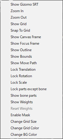
If you narrow the window so that the toolbar cannot be displayed, a ![]() mark appears at the right end of the toolbar. Click this mark to open a menu list of buttons that are not visible. Select this menu to perform the function of each button.
mark appears at the right end of the toolbar. Click this mark to open a menu list of buttons that are not visible. Select this menu to perform the function of each button.
The menu image is for when all buttons are hidden. The actual menu displays only the hidden buttons.
Display portion of the layout
Display portion of the layout allows you to directly select the Part used in the animation, allowing you to perform intuitive operations such as transforming and moving Part.
Explains how to work in the Display portion of a layout.
Basic Operations
Switching Data to Edit
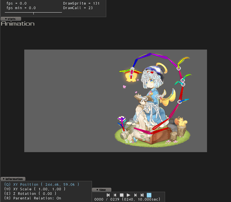
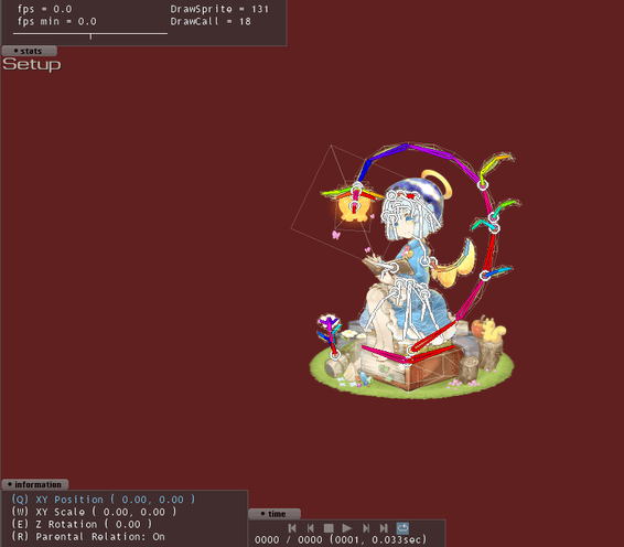
You can switch the data you are editing by clicking “Animation” or “Setup”.
Click while viewing animation data to switch to setup data, or click while viewing setup data to switch to animation data.
| When Animation Data is displayed | When Setup Data is displayed |
The background color of the layout window changes when the Setup Data is displayed.
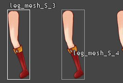
Select Part
Click a visible Part to keep it selected.
Select Multiple Parts
+ click the displayed part to select multiple parts simultaneously.
Select multiple Parts within a region
By selecting a range, you can select all Parts within the range.
Clear Selection State
“Ctrl + click” the selected Parts to clear the selection.
Move Display Range
+ drag to move the display range.
Operations on selected Part
The selected Part can be manipulated as described below.
Movement, deformation, etc.
The selected Part can be moved or transformed.
| Drag Part | Move the placement of the Part. |
|---|---|
| Drag four corners or edges of a Part | Change the scale. |
| + drag corners of a Part |
Manipulate the Part “Vertex Deformation”. |
| Drag rotation handle |
Rotate Z. |
About Working with Mesh Parts
The selected mesh Part can be deformed by moving its set vertices
See the link below for more information.
About Working with Joint Part and Bone Part
The selected Joint and Bone Part can be animated by adjusting the position, scale, and angle of the Mesh Part.
See the link below for more information.
About Working with Part IK
When you move a Part with + drag, the part moves with the “Inverse Kinematics” function enabled. Inverse kinematics is the ability to move the Parent Part in relation to the moved Part.
The extent to which Inverse Kinematics moves with the Parent Parts can be set in the “Part IK” item in the Layout Info Window.
How to switch a selected Part to the Part shown in the front or back
With a Part selected, press the and keys to cycle through the Parts displayed in front and back of the selected Part.
This is useful when you want to select a Hair Part that is hidden by a Part of your body, or when you want to change the selection of a small accessory Part.
| Select the Part behind the selected Part. | |
| Select the Part displayed in front of the selected Part. |
Context menu for selected Part
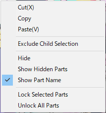 Right-click the selected part to open the context menu. Each menu is described below.
| Cut | Copies the selected Part and its children to the clipboard and then deletes them. |
|---|---|
| Copy | Copies the selected Part and its children to the clipboard. |
| Paste | Adds a Part copied to the clipboard with “Cut” or “Copy” as a new Part. |
| Exclude Child Selection |
Clears the selection except for the Parent Part. Unselect all Child Parts by doing this when multiple Parts are selected. |
| Hide | Hides selected Parts. |
| Show Hidden Parts |
Switch all hidden Parts to show. |
| Show Part Name |
Shows or hides Part names. Changes the visibility of the selected Part Name to the Part Name at the cursor.
|
| Lock Selected Parts |
Locks the selected Part. Locked prevents Part selection and attribute changes.Use locks if you do not want to accidentally manipulate Parts. |
| Unlock All Parts | Unlocks all Parts. |
Viewing and manipulating animation information
Describes the menu that appears in a small window that opens and closes by clicking the small buttons at the corners of the visible portion of the layout.
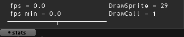
| stats |
Displays the number of frames per second (fps), DrowSprite, and DrawCall during animation playback. The numbers of DrowSprite and DrawCall are the numbers when played back in SpriteStudio. When data is reproduced in another environment, there will be differences, so please use them as reference values. |
|---|---|
|
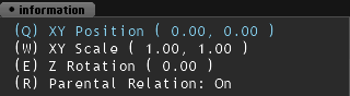
information |
Displays attribute information about the selected Part. Press the “Q”, “W”, “E”, or “R” keys to make the corresponding attribute change using the arrow keys.
|
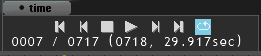
| time |
Contains buttons for animation playback controls. The buttons are the same as those on the bottom toolbar of the Frame Controls window.
|
Note: Null parts can be manipulated by displaying a gizmo or focus frame.
Clicking in the layout window automatically selects the part at the clicked location.
Related Pages
- Layout Info Window
Describes the Layout Info Window.