
The “Animation” is the frame data for creating a certain “single movement” by using one or plural “Cells”.
- First, an animation file is created in order to store data. Select either menu of the following:
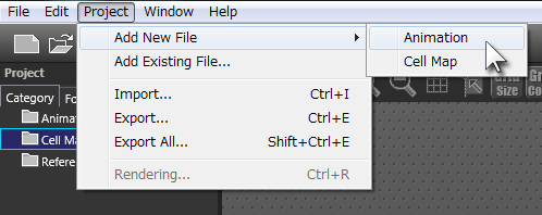
- Choose [Project]-[Add New File]-[Animation] from the upper menu
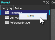
- Or, right-click the cell map of the “Project” window and choose [New]
- Choose [Project]-[Add New File]-[Animation] from the upper menu
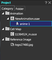
- The window for selecting the folder and the file will open. Specify the animation filename. The filename specified herein will become the name to be displayed in the “Animation” of the “Project” window.
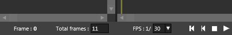
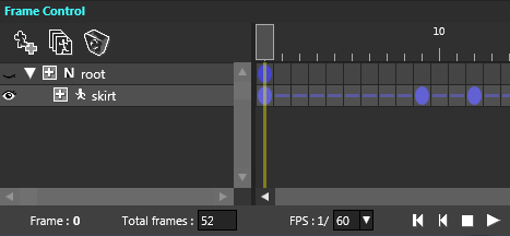
- After the animation was created, the “Frame Control” operation will be enabled. At the “Total Number of Frames” located at the lower part of the “Frame Control” window, the whole length of the animation is set based on the “Number of Renewal Frames per second (FPS)” of the “unit time”.
- In the “Layout Info” window, the whole size of the animation (the size of animation-exclusive screen frame) to be created is set.
- Then, select the cell from the “Cell List” window, which is used for animation, and drag and drop it in the “Layout” window.
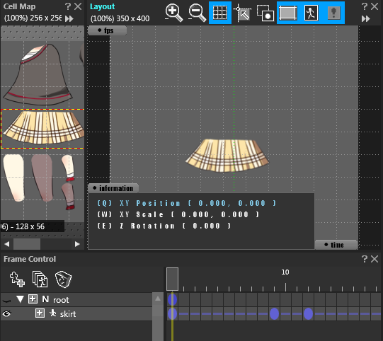
If dropped normally, the cell is displayed at the dropped location and the dropped cell name is displayed as “Parts” in the “Frame Control” window.
When the cell is dragged and dropped and made to be parts, care must be taken that the part’s initial information (the first Key-Frame) is placed at the frame position selected on the “Frame Control” window.
- Select the parts to be set in the “Layout” window or in the “Frame Control” window.
- The inheritance relation with other parts is set.
The inheritance relation (also said “parent-child relation”) is to string other parts when the parts is required to jointly work with other parts’ movements On the “Frame Control” window, a inheritance relation can be created by dragging and dropping the parts onto the parts of origin of inheritance.
With the parts with the relation of inheritance, the origin of inheritance is called “Parent Parts”, and the parts placed under the inheritance is called “Child Parts”. In principle, the setting value of the child parts is a relative value from the parent parts.
To remove the relation of inheritance, by dragging the child parts in the “Frame Control” window, drop it just under the child parts (the blue and dim underline appears), then the relation is canceled.
- After clicking the frame position needed on the “Frame Control Window”, the Key-Frame can be created by doing the “Add Key” from the right click menu.
At this Key-Frame position, a variety of parts’ information can be set. The Key-Frame can also be created from other various functions. For example, it can be created also by the method of clicking within the Interpolation curve during specifying “Interpolation” of the “Attribute” window.
- The position and size of the parts are set either by visually set the position, the scaling rate and the twirl angle, or their values are set by values, etc. which are displayed in the “General” of the “Attribute” window.
In case of visually adjusting in the “Layout Window”, the Move, Scale and Rotate can be easily implemented by using “Gizmo”. In case of making adjustments of values in the “General” in the “Attribute” window, proceed with the following method.
- Click the position of the value of the setting attribute. Then, the value can be input directly.
- By keeping the click action (the button is kept pressed) to the “Each Part of Attributes” of the setting attribute and by moving the mouse vertically, the value can be changed continuously, I.e., upwards => + and downwards => -.
- As for the attribute, the value of which unnecessary to be fixed at its Key-Frame, it is recommended that the “O” mark located at the front of each attribute of the “General” in the “Attribute” window. (The final data is made small.)
By repeating these procedures, animation can be created. For a single animation, the procedural order of 3. to 9. can be changed with no problem. Just remember the above as one of the operational example.
Note:
At the initial state of starting “OPTPiX SpriteStudio”, many attributes of the “Attribute” window “General” are displayed. If the object attribute is difficult to find during editing, select [File]-[Project Settings]-[Compatibility] of the upper menu bar and choose the object platform or “Custom”. Then, only the necessary attributes can be displayed.
In that instance, it is possible to select “the attribute ‘making the setting state’ upon placing the key-Frame at first”, but if the attribute holding check therein has been made to no display at the [Compatibility], the value cannot be changed at any time. So, care must be taken as for the correlation of the set values.
To be more, the setting for the editing project must be done from the [File]-[Project Setting]. There is a similar kind of setting with the [File]-[Preference], but this is for the object of the “Newly Created Project”. Therefore, it is not reflected upon the editing project.
The setting and operational methods of the “Frame Control” window and the “Layout” window cover a lot of ground, so please the related pages of the help explanation.
In principle, in case of not setting the priority of attributes, parts located downwards at the frame control shall be displayed nearer side. When the parent-child setting, etc. is done, or when there is the definite display order per every parts, be always sure to set the priority. In particular, when the output is made to other game engines such as Unity, there is no guarantee that the row of parts are just as it is with “OPTPiX SpriteStudio”. So, please remember that the priority always must be set.