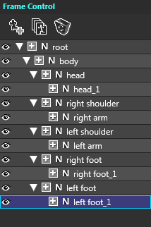
FAQ

Parts (Sprite)

About the actual range of selected keyframes to copy and paste while parts tree is collapsed.

Please note that keyframes of invisible parts which are collapsed in parts tree are not copied or pasted even if the keyframes of the parent part of them is selected.

To minimize the number of too many attributes to be used.

Attributes which can be set to the parts of Sprite exist in the considerably large number. So, unused attributes are better not to be displayed in the “Attribute” window. That will help reduce humanly errors.

The method of adjusting attribute’s display is different between the “Project’s new creating time” and the “already-existing Project”.

  1. The “newly created Project” is set by the compatibility of the window, which was opened by the [File]-[Preferences].

  2. The “already-existing Project” is set by the compatibility of the window that was opened by the [File]-[Project Settings].

The method of setting the “Compatibility” are the same each other. The are the following two setting methods.

1. To specify the “object Platform for play”.

After creating data by “OPTPiX SpriteStudio”, by selecting the platform to mount the data (hardware, OS, game engine, etc.) only attributes to match the platform can be displayed.

2. To “Custom” the “object Platform for play” by the self:

By setting ” the object Platform for play to Custom”, only attributes marked by the self can be displayed.

Also, after selecting the above and by selecting the “Limit to Ver.4 compatible functions”, the data usable by “SpriteStudio Professional” can be created without displaying/outputting attributes added at the “OPTPiX SpriteStudio”.

ON/OFF of the setting of the Part’s Attribute.

The round mark at the front of each attribute which is found in the “General” of the “Attribute” window is for judging if “the attribute is used (set) in that Key-Frame”.

ON/OFF of the setting of the Part’s Attributes

  • If the round mark is blue, “the attribute is being used in the Key-Frame”.
  • If the round mark is white (shallow gray), “the attribute is not used in the Key-Frame”.

How to use NULL parts?

The “NULL parts” is the special Sprite parts.

This is the parts “without cell to be displayed” and “with attribute only”.

By making a good use of the “Null parts”, it is also possible to create animations with complex joint’s structure and movements.

To add the “NULL parts”, there are the following two methods:

  1. Press the “Add NULL Parts” button located at the upper menu of the “Frame Control” window.
  2. Do the right click at the “Frame Control” window and select “Add NULL Parts” at the menu displayed thereby.

The following are some “typical use of the NULL parts”:


1. As the “Reference Position of Sprite animation”

When moving a created Sprite animation from programs, etc., the movement is normally given to the “root parts (located uppermost of each animation and named as the “root” parts just after its creation)”. The “root parts’ positional point” is conveniently called a “representative point” herein. Then, which position is the best when this “representative point” is considered as the reference point of the whole animation to create?

As an example, there is an “animation of the running human (and animals)”. In that instance, the representative point is often placed to the ground point of the foot. However, there are frequent cases that the work becomes easier if the animation’s reference point is placed to the center of the body or alike.

In this case, the root parts is specified as the ground point and one NULL parts is specified just under the root parts for controls from the program. Thereafter, by creating all the parts as the “child of the NULL parts”, it will enable to “create the animation with the reference point of the body center by taking the ground point as the representative point”.

As the “Reference Position of Sprite animation”

In the example of the above figure, the “green X mark” is the “root parts’ position (representative point) and the “red round mark” is the “animation’s reference point”. The red arrow indicates the parent-child relation (The origin is parent and the destination is child.)


2. As the “reference position to let the hand hold something”

Now, let’s see an example of creating the “animation of something held in the hand”. In such instance, it is convenient if the NULL parts is created as the child of “hand’s parts” as for designating the mark/position of “holding something at this position” as the “character’s hand” position.

Especially in such cases as “Something held changes”, “Something held is influenced by the hand’s movements”, it will be easy to “replace something held” if the NULL parts is already set as the reference point of holding”. In addition, if a certain rule of the NULL parts’ names etc. is decided in advance the process will be often easier to “change something held from the application program’s side.”

3.As the “bone” of animation with joints

As the “bone” of animation with jointsTo create 3D graphic animation, the “scheme to control each part of animation is created. It is called the “bone (or skeleton, previously)”. The 3D model data created by the common bone can commonly share the “movement data” in principle and can increase the efficiency of creating animations and alike. With “OPTPiX SpriteStudio” too, parts can be placed in the form of bones by building the parent-child relation with plural NULL parts.

For example, by building the right “Parent-Child Relation” with NULL parts and by attaching Sprite parts of respective regions as children of the respective NULL parts, animations of various poses can be created. Then, if the Sprite part is replaced by another one, it is also possible to create the same animation as another character.


Likewise, the “NULL parts” has very important roles and merits as the parts to create “positions and movements of reference”. By combining the above three roles, “systematized” animations with “smooth movements”, even if considerably complex, can be created easily and conveniently.

The NULL parts has a considerably diversified use, so please try various ways so as to discover true merits of its use.

Also, items of this chapter are referred to the “Parent-Child Relation” of the “FAQ: Sprite Animation” .

The Setting Differences of inheriting (of Key-Frame Parameters) to SpriteStudio Professional and OPTPiX SpriteStudio

The “Inheritance Settings” is a functionality to set up which attribute value that is set at the parent parts will affect child parts or not.

With the “SpriteStudio Professional”, “Succeed or No Succeed” and the “succession ratio (effect ratio)” could be set per each attribute. But with the “OPTPiX SpriteStudio”, the functionality has been widely changed.

With the “OPTPiX SpriteStudio”, each attribute value is made for the “Inheritance settings”. The instances allowing to select the “Inheriting or Not Inheriting” are the following cases only: “Opacity”, “Horizontal Flip”, “Vertical Flip”, and “Hide”.

This change has been made in order to avoid troubles arising from the specifications and erroneous settings of hardware and game engines (as of the last year 2012).

Cell Map, Cell List, Cell and Reference Image

To change reference image (texture) during and after creating animation

As cases to change reference image of the creating project, there may be the following two situations: “To replace the reference image file to another file” and “To edit the reference image itself”.

At first, in the situation: “To replace the reference image file to another file”, do the following operation.

  1. Right click on the “Cell Map”.
  2. Select the “Change Reference Image” of the menu.

Also, in the situation: “To edit the reference image itself”, do the following operation.

  1. Select the desired image to change that exists in the “Reference Image” of the “Project” window.
  2. Press the right click. The menu “Show in Explorer” will appear. Then, select it and specify “the file which is used actually”.
  3. Save the project once and end “OPTPiX SpriteStudio”.
  4. Start the specified image by the graphic tools (OPTPiX imest, etc.), and process and save.
  5. Again, start “OPTPiX SpriteStudio”, and open the project which had been created up to 3).

However, in either case of “To replace the reference image file” or “To edit the reference image”, and when the cell placement in the reference image has changed, it is necessary to readjust the cell cutout range. In this situation, when the pixel-size (of reference image) was simply scaled up or down with no change of the cell placement itself within the reference image, the cell cutout information will be changed automatically.

To search object cell

The “Cell List” gathers cells and is managed for every “Cell Map” individually. Therefore, use either method of the following in order to find to which cell list the cell used by the animation part belongs.

  1. When the object parts are clicked on the “Frame Control” window, the object cell can be selected on the cell list.
  2. When the object parts are clicked on the “Layout” window, the object cell can be selected on the cell list.
  3. When each item in the “Cell Map” of the “Project” window is selected, the cell list selected from the cell map is displayed in the “Cell Map” window, and the check can be done whether the related cell is therein or not.

Project

How are environmental settings and project settings related?

Environmental settings are information about settings saved for each user.

They are saved in the SsOption.ssop file in My Documents/SpriteStudio.

The settings in the project menu are information about settings saved for each project. They are saved in the *.sspj file.

When a new project file is created, the project setting contents are determined by inheriting the “Project Default Settings” of the environmental settings.

So note that when the project default settings for the environmental settings are changed after creating or loading a new project, the changed settings are not used.

What is the Reference Folder?

In SpriteStudio, the location where the animations and cell map files registered in a project exist are saved as the relative path from the project file (.sspj) folder + reference folder.

So, by changing the reference folder and using the same file name, data with different content is loaded, so, for example, an application may be to create Japanese-language and English-language images or cell map files, and switch them out for confirmation.

The following are cautions when changing the reference folder after registering files.

Examples:

When the reference folder is empty, the following 3 files are registered in the project.

SsProject.sspj
  Animations/
    anime.ssae
  Cellmaps/
    cellmap.ssce
  Images/
    image.png

In this situation, the following file names are registered in the project file.

Animations/anime.ssae Cellmaps/cellmap.ssce

A list of cell map file names that are reference are registered in anime.ssae.

Cellmaps/cellmap.ssce

Reference image file names are registered in cellmap.ssce.

Images/image.png

Note:that with this situation, the above registered file names are not changed even iv the reference folder is changed.

For example, if EnglishImages is specified in the reference image reference directory, and the project is restarted, EnglishImages/Images/image.png rather than Images/image.png will be loaded.

In other words, be aware that the reference folder must be set before files are registered.

Specific procedures include creating the necessary reference folder in the folder where the project file is saved before creating the project file, or creating a reference folder on the project settings screen after creating a new project file, and then start to create the animation and cell maps after reloading.

Note:A reference folder is automatically created if one does not exist when a project is loaded.

Why is .ssce display updated when importing several .ssax files that share the same image?

When the first .ssax file is imported, a new .ssce file is created and saved. When a new cell is added when importing the next .ssax file, the status becomes an update state.

Because, when a second or subsequent .ssax file is imported to a cell map that has already been added to the project, the .ssce file is treated as though a change has been made, the result is that auto save is not performed implicitly and the update display is as-is.

Other

I want to know how to deactivate license.

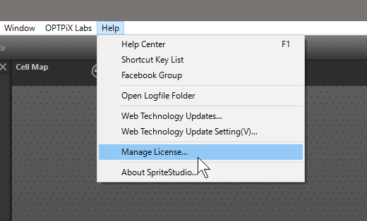
1. Select the “Manage License” in the Help menu

deactivate1

2. Click “Deactivate license”.

deactivate2
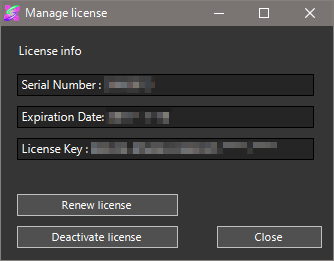
3. Close SpriteStudio, And deactivate at the end of the program.

“UV X/Y Translation” and “(change of) Reference Cell” of the single animation

As the method of changing, with Key-Frame attributes, the image drawn by the Sprite’s parts, the following two ways are available with “OPTPiX SpriteStudio”.

  • To Change the “Reference Cell”.
  • To use “UV X/Y Translation”.

There is the basic rule to distinguish the use of these ways.

The method to “Change the Reference Cell” of 1. is the same method used by the “Frame Anime Method”. For example, “(eye) blinking”, “lip sync”, “replacement of the item held in hand”, etc. are handled by this method.

The method of “UV X/Y Translation” is the method used to “Scroll the image in the Sprite”. For example, “Wafting clouds”, “Flowing/shaking water surface”, “Floating mist”, etc. . are handled by this method. Basically different from 1., it is used as one tool of the “Key-Frame Method”.

With these two methods, the objectives of the “attribute” are clearly different but “the same task” can be accomplished depending upon how to use them. To be accurate, the method of 2. can replace the method of 1. but not vice versa. In a concrete meaning, the same effect as the “Change of Reference Cell” can be obtained by setting one Reference Cell and then setting “UV X/Y Translation” with “No interpolation” in the Key-Frame.

However, these two methods must not be used in mixture as the method of creating specific animations even if the same objective can be accomplished. If used in mixture:

  • The content of data becomes not easy to understand.
  • The maintenance and modification of data becomes difficult.

These abuses will cause “The other people cannot understand the content of data”, especially when the work is done jointly with other people.

Therefore, it is recommended that the animation data must be created in the form of unified use of the available methods thereby meeting objectives.

Processing becomes slow when exported to game engines, etc

Nowadays, there are many GPUs (Graphic Processing Units) with the following features.

  • Much time is required for switching textures used for processing.
  • The square texture used for processing can be processed at higher speed.

For these reasons, with the “OPTPiX SpriteStudio”,

  • The number of the cell maps used by animation is reduced.
  • The cell maps are better made to be square with four corners of 2n (2 powered by n) pixel.
  • The cell map must ideally be used commonly even if plural animations.

By implementing these matters, the drawing speed may be increased.

The content of this chapter is also referred to regarding:

Where is the description about SSPJ/SSAE/SSCE file format?

The overview about the formats of sspj/ssae/ssce file which OPTPiX SpriteStudio 5 handle can be found in SpriteStudio 5 SDK.

Please look into the “documents” folder on the below page.

»SpriteStudio 5 SDK page

For more information about the meaning of tags, how to load and to handle them, please refer to the C++ source code(like ssloader_ssae.* etc…) in “loader” folder.

The Sprite’s position is misaligned when play

When data is mounted to the application, there are such cases as the Sprite parts are misaligned or the parts show unexpected movements of blurring.

In particular, they are the symptoms appearing when using rotation and scaling.

When these symptoms appear, check:

  • If the origin (the pivot pixel position) of the cell is an odd number.
  • If the size of the cell is an odd number.

If so, modify “the origin (the pivot pixel position) of the cell” and “the size of the cell” to become even numbers without fail.

However, there are some cases that the above symptoms will appear even when the cell size and the original point position are even numbers.

The content of this chapter is also referred to : “The cautions for placing each animation parts to the texture” in “Sprite Animation” .

What is the origin position for the layout information?

With version 4, the origin was always at the top left of the reference frame.

For this reason, in order to have the origin at the feed of the character, as in the sample comipo data, the XY coordinates of the root part must be set to be near the feet of the part that is to be the reference point.

However, if this is done, because, for example with SSP for Unity, XY for the root parts is unnecessarily offset when a different animation is suspended off of some parts of another animation, it becomes necessary to set the XY for the root parts to 0,0 to avoid this.

But when doing this, on Version 4, since the origin is the top left of the reference frame, portions positioned higher and more to the left of the reference frame may not be visible because the fall outside of the layout window.

Note: The XY for root parts is ignored with SSP for Unity.

So, the troublesome operation of making the [Margins] for [Animation Settings] large, and setting values so that the root parts origin is generally in the center of the layout window, were necessary to avoid this situation.

Essentially, animations that were to be expressed on the entire screen, in other words ones that were created with a layout that has UI parts arranged, are standard, and are no suitable for creating simple character animation in which the pivot is placed somewhere other than the top left, in other words the center or feet.

This feature was added so that for either application, this could be switched with a single origin setting. However, the margin settings have been eliminated instead because usage was limited.

Is it possible to use in tablet mode of Windows 10?

Use in tablet mode is not supported.Because there is a specification on the problems of the tablet mode.

Please be used in desktop mode in Windows 10.